This will be an unusual blog post. We will talk about probably the most important peace of Information in Computing – BIT. What is a Bit? Essentially, Bit represents the smallest amount of electricity – either it is present (bit 1) or it is not (bit 0). A bit is also the smallest unit of information. It’s a binary digit, representing either a 0 or a 1. This simple binary system is the language of computers, the basis of all digital information.

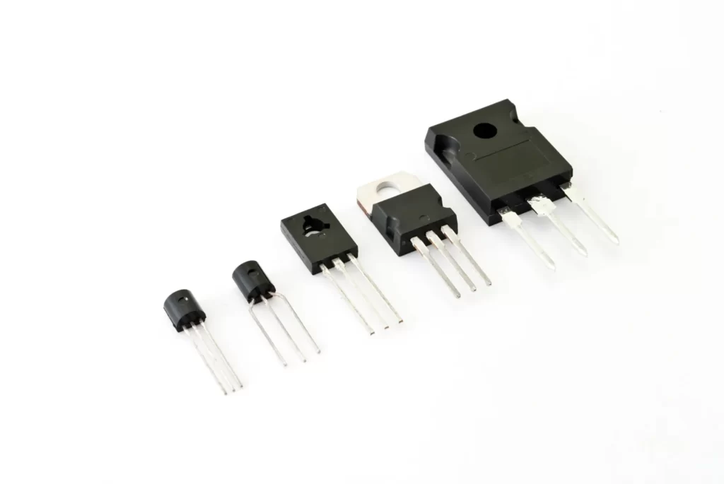
Now, you might wonder, how do we physically represent these bits in a computer? This is where transistors come in. While it’s not entirely accurate to say that a bit is a transistor, transistors are indeed the physical components that allow us to manipulate and store these bits of information.
How Transistors Work: A Beginner’s Guide
To understand transistors, we need to start with some basic ideas about matter and electricity.
The Building Blocks
Everything around us is made of tiny particles called atoms. Atoms themselves are made of even smaller particles. The ones we care about for understanding transistors are:
- Protons: These have a positive electrical charge.
- Electrons: These have a negative electrical charge.
- Neutrons: These have no electrical charge.
Protons and neutrons stay in the center of the atom, while electrons move around them.
Electricity and Materials
Electricity is essentially the movement of electrons. Some materials allow electrons to move easily through them – we call these conductors. Others resist the movement of electrons – we call these insulators.
There’s a special group of materials that can behave sometimes like conductors and sometimes like insulators. We call these semiconductors. The most common semiconductor used in electronics is an element called silicon.
Making Silicon Special
Pure silicon doesn’t conduct electricity very well. But we can change its behavior by adding tiny amounts of other elements to it. We call this process “doping.”
When we add elements that have extra electrons, we create what we call “N-type” silicon. The “N” stands for negative, because of the extra electrons.
When we add elements that have fewer electrons, we create spaces where electrons could be. We call this “P-type” silicon. The “P” stands for positive, because the spaces act almost like positive charges.
Building a Transistor
Let’s build a transistor step by step, focusing on the most common type called a MOSFET (Metal-Oxide-Semiconductor Field-Effect Transistor).
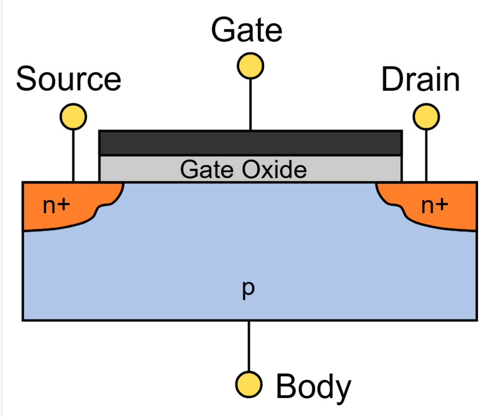
- Start with a flat piece of silicon. This is called the “substrate” and forms our foundation. For an N-type MOSFET, this substrate is P-type silicon (has extra holes).
- In this piece of silicon, we create three distinct regions side by side:
- A region called the “source”
- Next to it, a region called the “channel”
- Next to the channel, a region called the “drain”
- The source and drain are made of silicon that has been “doped” to have extra electrons (N-type). Let’s consider a typical N-type MOSFET for this example:
- The source is N-type silicon (extra electrons)
- The channel is P-type silicon (extra holes)
- The drain is N-type silicon (extra electrons)
- Above the channel, we add a very thin layer of insulating material. This is typically silicon dioxide, which doesn’t conduct electricity.
- On top of this insulating layer, directly above the channel, we place a conductive material. This is the “gate”.

So, from bottom to top, right above the channel, we have:
- The silicon channel (npn body)
- The thin insulating layer (gate oxide)
- The gate
And from left to right, we have:
- Source (N-type)
- Channel (P-type)
- Drain (N-type)
The gate doesn’t touch the channel directly – it’s separated by the insulating layer. But it can still affect the channel through this layer.
How It Works
- Normally, electrons can’t flow easily from the source to the drain because the P-type channel is in the way.
- When we apply a positive voltage to the gate:
- It creates an electric field that passes through the insulating layer
- This field attracts electrons into the channel
- If the voltage is high enough, it draws so many electrons that it creates a thin layer of N-type silicon in the channel
- Once this N-type layer forms in the channel:
- We have a continuous N-type path from source to drain
- Electrons can now flow freely from source to drain
- The transistor is “on”
- When we remove the voltage from the gate:
- The electrons in the channel disperse
- The channel returns to its normal P-type state
- Electrons can no longer flow easily from source to drain
- The transistor is “off”
This ability to control the flow of electrons with the gate voltage is what makes transistors so useful in electronics.
Why Electrons Don’t Flow When the Transistor is Off
You might wonder: “If the source is N-type (extra electrons) and the channel is P-type (extra holes), shouldn’t the electrons naturally flow from the source to the channel?” This is a great question, and understanding the answer helps us grasp how transistors work.

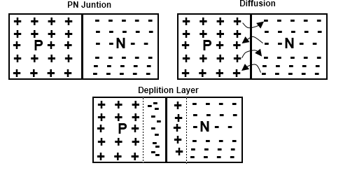
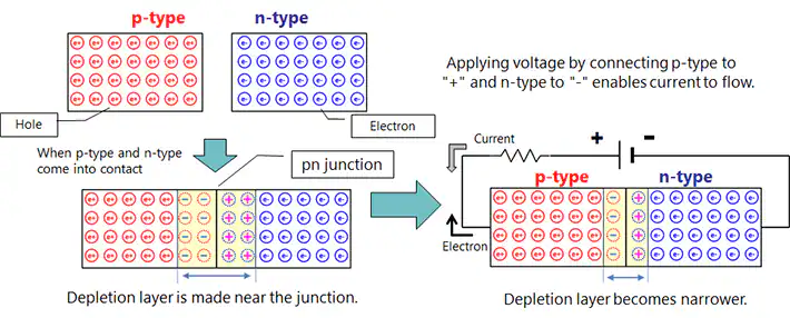
- PN Junctions: When N-type and P-type silicon meet, they form what’s called a PN junction. At this junction, some interesting things happen:
- Some electrons from the N-type side move to the P-type side.
- Some holes from the P-type side move to the N-type side.
- This creates a small area called the “depletion region” at the junction.
- The Depletion Region:
- This region has no free electrons or holes.
- It acts like a barrier between the N-type and P-type regions.
- It creates an electric field that opposes further movement of electrons and holes.
- In Our Transistor:
- We have two PN junctions: one between the source and channel, and one between the channel and drain.
- Each junction has its own depletion region.
- These depletion regions act as barriers, preventing easy flow of electrons from source to drain.
- Why Voltage Matters:
- To get electrons to flow, we need to overcome these barriers.
- The voltage applied to the gate can change the size of these depletion regions.
- When we apply the right voltage to the gate, it can effectively remove these barriers, allowing electrons to flow.

So, even though the P-type channel has “holes” that might seem attractive to electrons, the depletion regions at the junctions prevent easy flow. This is why the transistor is “off” until we apply the right voltage to the gate.
Controlling the Flow of Electrons
In this journey through the world of transistors, we’ve uncovered the fundamental building blocks of modern computing. From the basic concept of a bit to the intricate workings of a MOSFET, we’ve seen how these tiny electronic switches form the backbone of our digital world.
Transistors are truly remarkable devices. By manipulating the flow of electrons at a microscopic level, they allow us to represent, process, and store the binary information that underlies all digital technology. Their ability to switch between “on” and “off” states, controlled by small changes in voltage, is what enables the complex calculations and operations performed by our computers, smartphones, and countless other electronic devices.
Think for a bit about the complexity of our technological world, one can say at the fundamental it’s all about the controlled flow of electrons.
Enhanced Interactive MOSFET Transistor
Gate Voltage: 0V
Transistor is OFF
